Fuel sensor GW 7-0001
Description
Features – the Fuel Sensor is equipped with suction and returning of fuel.
Material – antimagnetic stainless steel.
The basic construction component is a flange to which tubes are welded. The measuring system is placed inside the central tube of 12mm diameter. The float with a magnet moves along this tube and operates the magnetic switches. As a result, the output resistance value depends on the fuel level in the tank.
Two smaller tubes of 8mm diameter serve for suction of fuel (or its returning) from/to fuel pump. A filter is provided to prevent intrusion of rough impurities from the return pipe to the suction pipe. Ends of these tubes above the tank are provided with a reinforcement to secure a reliable connection of hoses.
The Fuel Sensor is intended for mounting to tanks with a 40mm hole.
The use of the fuel gauge must be specified in the order.
Parameters
| Max. voltage | 15 | V |
|---|---|---|
| Max. current | 150 / 200 | mA |
| Operating temperature | -40°C to +85°C | °C |
| Label | Producer, product code, direction of fuel flow, date (or date code) | |
| Vibration resistance | 3 | g |
| Service life | 1 000 000 | cycles |
| Protection degree | IP 68 (Inner part) | IP 67 (External part) |
Limit parameters for specifying new types by the customer
| Max. length H | 900 | mm |
|---|---|---|
| Measuring circuit resistance | 50 – 100 000 | ohm |
| Minimum measurement step | 16 | mm |
| Max. measured height L1 | 30 | mm |
| Min. measured height L0 | H-30 | mm |
| Connector | Any type of cable connector | |
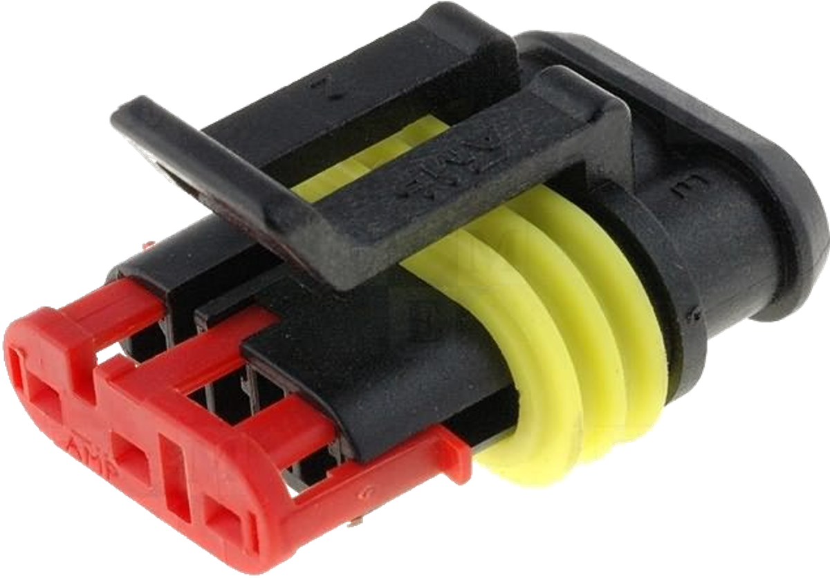
Examples of connectors used:
-
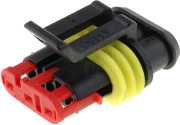
- SuperSeal 282087-1
-

- SuperSeal 282105-1
-
- Weather-Pack 12010974
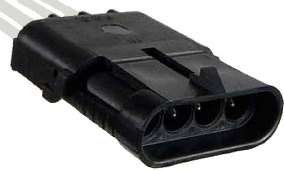
-
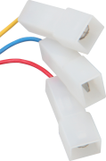
- Faston 6,3×0,8

-
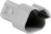
- Deutsch DT04-3P
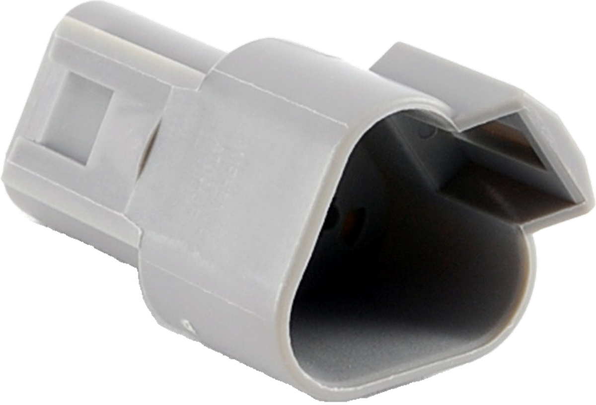
-
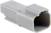
- Deutsch DT04-2P

-
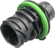
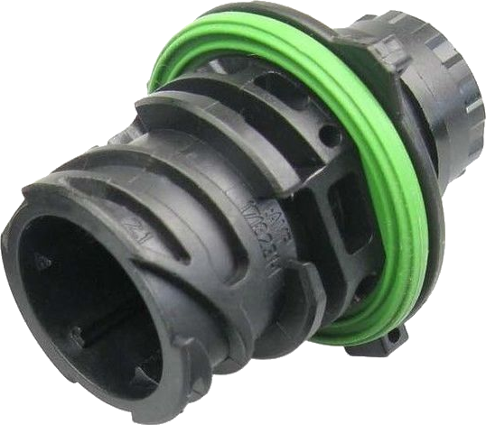
- 1-967402 ; 1718230
Fuel sensor GW 7-1001
Description
Material – antimagnetic stainless steel
The basic construction component consists of a flange and square tube welded together. The measuring system is placed inside the tube. The float with a magnet moves along this tube and operates the magnetic switches. As a result, the output value of the selected electrical quantity depends on the fuel level height.
The Fuel Sensor can be equipped with a reserve switch.
The measurement system can be connected as a rheostat or as a voltage divider.
The Fuel Sensor is intended for mounting to tanks with a 40mm hole.
The use of the fuel gauge must be specified in the order.
Parameters
| Max. voltage | 32 | V |
| Max. current | 50 | mA |
| Operating temperature | -40°C to +85°C | °C |
| Label | producer, producer code, date (or date code) | |
| Vibration resistance | 3 | g |
| Service life | 1 000 000 | cycles |
| Protection degree | IP 68 (inner part) | IP 67 (external part) |
Limit parameters for specifying new types by the customer
| Max. length H | 1500 | mm |
| Measuring circuit resistance | 50 – 100 000 | ohm |
| Minimum measurement step | 10 | mm |
| Max. measured height L1 | 18 | mm |
| Min. meausered height L0 | H-22 | mm |
Examples of connectors used:
-
- SuperSeal 282087-1
-
- SuperSeal 282105-1
-
- Weather-Pack 12010974
-
- Faston 6,3×0,8
-
- Deutsch DT04-3P
-
- Deutsch DT04-2P
-
- 1-967402 ; 1718230
Fuel sensor GW 7-2021
Description
Material – flange PBT; tube – antimagnetic stainless steel.
The basic construction component is a plastic flange in which a stainless steel tube is moulded. The measuring system is placed inside the tube. The float with a magnet moves along this tube and operates the magnetic switches. As a result, the output resistance value depends on the fuel level in the tank.
The output signal is provided by means of a two-pole sealed connector moulded in the flange.
The Fuel Sensor is intended for mounting to tanks with a 19/16″ thread.
The use of the fuel gauge must be specified in the order.
Parameters
| Max. voltage | 100 | V |
| Max. current | 50 | mA |
| Operating temperature | -40°C to +85°C | °C |
| Label | ||
| Vibration resistance | 3 | g |
| Service life | 1 000 000 | cycles |
| Protection degree | IP 68 (inner part) | IP 67 (external part) |
| Flange thread | 19/16 12UN-2A | |
| Max. tightening torque | 10 | Nm |
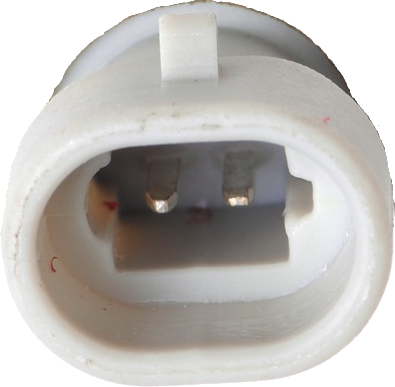
| Connector | DELPHI 12084669 (designed for 12162197 housing) | |
Limit parameters for specifying new types by the customer
| Max. length H | 600 | mm |
| Loop impendance | 50 – 100 000 | ohm |
| Measuring circuit resistance | 10 | mm |
| Minimum measurement step | 10 | mm |
| Max. measured height L1 | 50 | mm |
| Min. measured height L0 | H-30 | mm |
Connector in detail
-
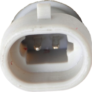
- Delphi 12084669
Fuel sensor GW 7-2501
Description
Material – flange PBT; tube – antimagnetic stainless steel
The basic construction component is a plastic flange in which a stainless steel tube is moulded. The measuring system is placed inside the tube. The float with a magnet moves along this tube and operates the magnetic switches. As a result, the output resistance value depends on the fuel level in the tank.
The output signal is provided by means of a two-pole sealed connector moulded in the flange.
The Fuel Sensor is intended for mounting to tanks with a 19/16″ thread.
The use of the fuel gauge must be specified in the order.
Parameters
| Max. voltage | 100 | V |
| Max. current | 50 | mA |
| Operating temperature | -40°C to +85°C | °C |
| Label | producer, producer code, date (or date code), customer identification | |
| Vibration resistance | 3 | g |
| Service life | 1 000 000 | cycles |
| Protection degree | IP 68 (inner part) | IP 67 (external part) |
| Flange thread/td> | 19/16 12UN-2A | |
| Max. tightening torque | 10 | Nm |
| Connector | DELPHI 12084669 (designed for 12162197 housing) | |
Limit parameters for specifying new types by the customer
| Max. length | 600 | mm |
| Measuring circuit resistance | 50 – 100 000 | ohm |
| Minimum measurement step | 10 | mm |
| Max. measured height L1 | 40 | mm |
| Min. measured height L0 | H-22 | mm |
Connector in detail
-
- Delphi 12084669
Fuel sensor GW 7-3012L;H
Description
Design:
- L – low resolution
- H – high resolution
Material – antimagnetic stainless steel.
The basic construction component consists of a flange and a square tube welded together. The measuring system is placed inside the tube. The float with a magnet moves along this tube and operates the magnetic switches. As a result, the output value of the selected electrical quantity depends on the fuel level height.
The measurement system is connected as a voltage divider.
The Fuel Sensor is intended for mounting to tanks with a 40mm hole.
The use of the fuel gauge must be specified in the order.
Parameters
| Max. voltage | 32 | V |
| Max. current | 50 | mA |
| Operating temperature | -40°C to +85°C | °C |
| Label | producer, product code, date (or date code) | |
| Vibration resistance | 3 | g |
| Service life | 1 000 000 | cycles |
| Protection degree | IP 68 (inner part) | IP 67 (external part) |
Limit parameters for specifying new types by the customer
| Max. height H | 1700 | mm |
| Resistance of the divider | 720 – 1800 | ohm |
| Max. voltage on divider | 10 | V |
| Max. voltage against body | 32 | V |
| Resolution – GW 7-3XXXL | 5,5 | mm |
| Resolution – GW 7-3XXXH | 2,5 | mm |
| Max. measured height L1 | 12 | mm |
| Min. measured height L0 | H – 12 | mm |
Examples of connectors used:
-
- SuperSeal 282087-1
-
- SuperSeal 282105-1
-
- Weather-Pack 12010974
-
- Faston 6,3×0,8
-
- Deutsch DT04-3P
-
- Deutsch DT04-2P
-
- 1-967402 ; 1718230
Fuel sensor GW 7-5020
Description
Design – the Fuel Sensor is completed with suction and backflow of fuel.
Material – antimagnetic stainless steel.
The basic construction component is a flange to which tubes are welded. The central tube is smaller and houses a measurement system. A float with a magnet moves along this tube depending on fuel level in the tank. By the magnetic field, the magnetic switches are operated. As a result, the output value of the selected electrical quantity depends on the fuel height in the tank.
The tube of 12mm diameter serves for suction of fuel, the tube of 10mm diameter is used for fuel backflow from the fuel pump. A filter is provided to prevent intrusion of rough impurities into the fuel system. Ends of these tubes above the tank are provided with a reinforcement to secure a reliable connection of hoses.
The Fuel Sensor is intended for mounting to tanks with a 40mm hole.
The use of the fuel gauge must be specified in the order.
Parameters
| Max. voltage | 15 | V |
| Max. current | 150 / 200 | mA |
| Operating temperature | -40°C to +85°C | °C |
| Label | producer, product code, direction of fuel flow, date (or date code) | |
| Vibration resistance | 3 | g |
| Service life | 1 000 000 | cycles |
| Protection degree | IP 68 (inner part) | IP 67 (external part) |
Limit parameters for specifying new types by the customer
| Max. length H | 900 | mm |
| Measuring circuit resistance | 50 – 100 000 | ohm |
| Minimum measurement step | 10 | mm |
| Max. measured height L1 | 15 | mm |
| Min. measured height L0 | H-30 | mm |
| Turn around of tubes | Different – depending on tank design | |
| Connector | Any type of cable connector | |
Examples of used connectors:
-
- SuperSeal 282087-1
-
- SuperSeal 282105-1
-
- Weather-Pack 12010974
-
- Faston 6,3×0,8
-
- Deutsch DT04-3P
-
- Deutsch DT04-2P
-
- 1-967402 ; 1718230
Fuel sensor GW 7-6111
Description
Material – Flange PBT; Tube – Aluminum.
The basic construction component is a plastic flange and a square tube. The measuring systém is placed inside the tube. The float with a magnet moves along this tube and operates the magnetic switches. As a result, the output value of the selected electrical quantity depends on the fuel level height.
The Fuel Sensor can be equipped with a reserve switch.
The measurement system can be connected as a rheostat or as a voltage divider.
The Fuel Sensor is intended for mounting to tanks with a 40mm hole.
The use of the fuel gauge must be specified in the order.
Parameters
| Max. voltage | 15 | V |
| Max. current | 50 | mA |
| Operating temperature | -40°C to +85°C | °C |
| Label | producer, producer code, date (or date code) | |
| Vibration resistance | 3 | g |
| Service life | 1 000 000 | cycles |
| Protection degree | IP 68 (inner part) | IP 67 (external part) |
Limit parameters for specifying new types by the customer
| Max. length H | 1200 | mm |
| Measuring circuit resistance | 50 – 100 000 | ohm |
| Minimum measurement step | 2,5 | mm |
| Max. measured height L1 | 18 | mm |
| Min. measured height L0 | H – 22 | mm |
| Connector | Any type of cable connector | |
Examples of connectors used:
-
- SuperSeal 282087-1
-
- SuperSeal 282105-1
-
- Weather-Pack 12010974
-
- Faston 6,3×0,8
-
- Deutsch DT04-3P
-
- Deutsch DT04-2P
-
- 1-967402 ; 1718230
Fuel sensor GW 7-7001
Description
Material – Flange: PBT; tube: antimagnetic stainless steel.
The basic construction component is a plastic flange with a central tube. The measurement system is located inside the tube. A float with a magnet moves along this tube and is operating the magnetic switches. As a result, the output value of the selected electrical quantity depends on the fuel height in the tank.
The Fuel Sensor can be equipped with a reserve switch.
The measurement system can be connected as a rheostat or as a voltage divider.
The Fuel Sensor is intended for mounting to tanks with a 40mm hole.
The use of the fuel gauge must be specified in the order.
Parameters
| Max. voltage | 15 | V |
| Max. current | 50 | mA |
| Operating temperature | -40°C to +85°C | °C |
| Label | producer, producer code, date (or date code) |
|
| Vibration resistance | 3 | g |
| Service life | 1 000 000 | cycles |
| Protection degree | IP 68 (inner part) | IP 67 (external part) |
Limit parameters for specifying new types by the customer
| Max. length H | 800 | mm |
| Measuring circuit resistance | 50 – 100 000 | ohm |
| Minimum measurement step | 10 | mm |
| Max. measured height L1 | 18 | mm |
| Min. measured height L0 | H-30 | mm |
| Connector | Any type of cable connector | |
Examples of used connectors:
-
- SuperSeal 282087-1
-
- SuperSeal 282105-1
-
- Weather-Pack 12010974
-
- Faston 6,3×0,8
-
- Deutsch DT04-3P
-
- Deutsch DT04-2P
-
- 1-967402 ; 1718230